blog
the current firmware can operate the switches and maintains counts of how many times a given contact has been closed(moved from NC to NO) as well as reporting the status
operation over USB and TCPIP are working
it is planned to add support for static IP addressing
the enclosure is coming along, the base holes have been drilled(but not countersunk) and the rear panel is marked up for the PCB mounted connectors. all front modifications are TODO
both the top and bottom PCBA have been produced
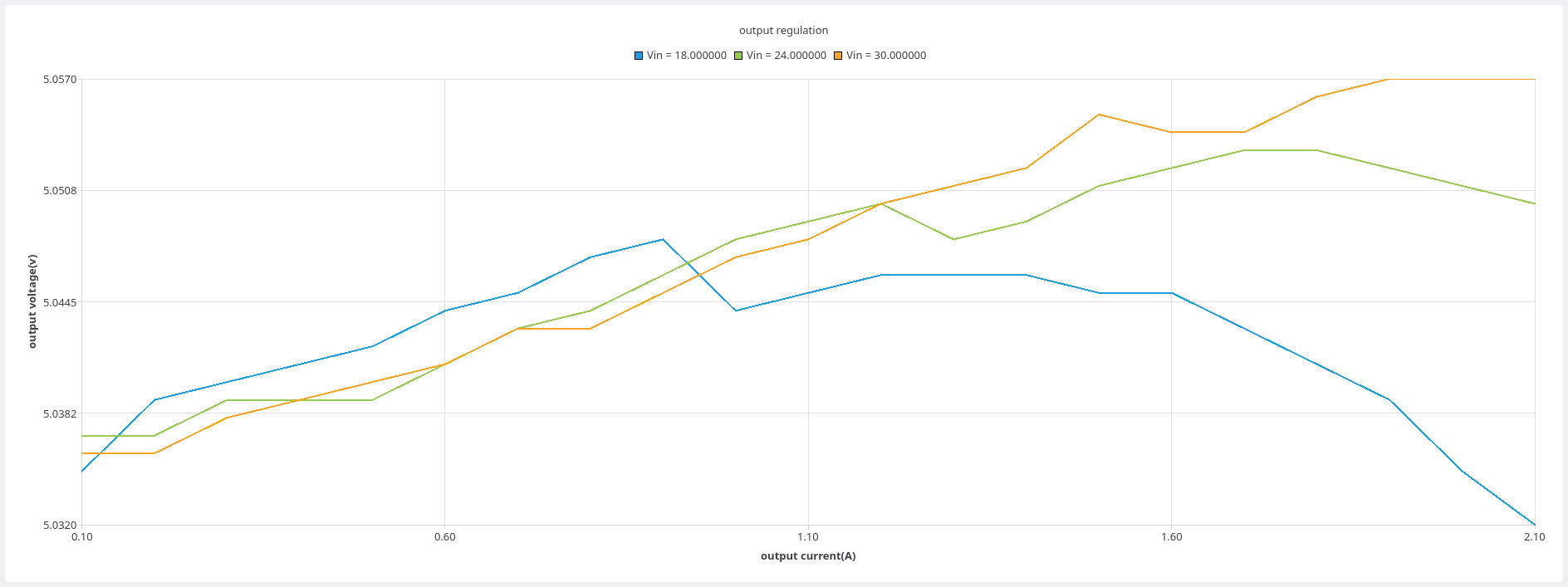
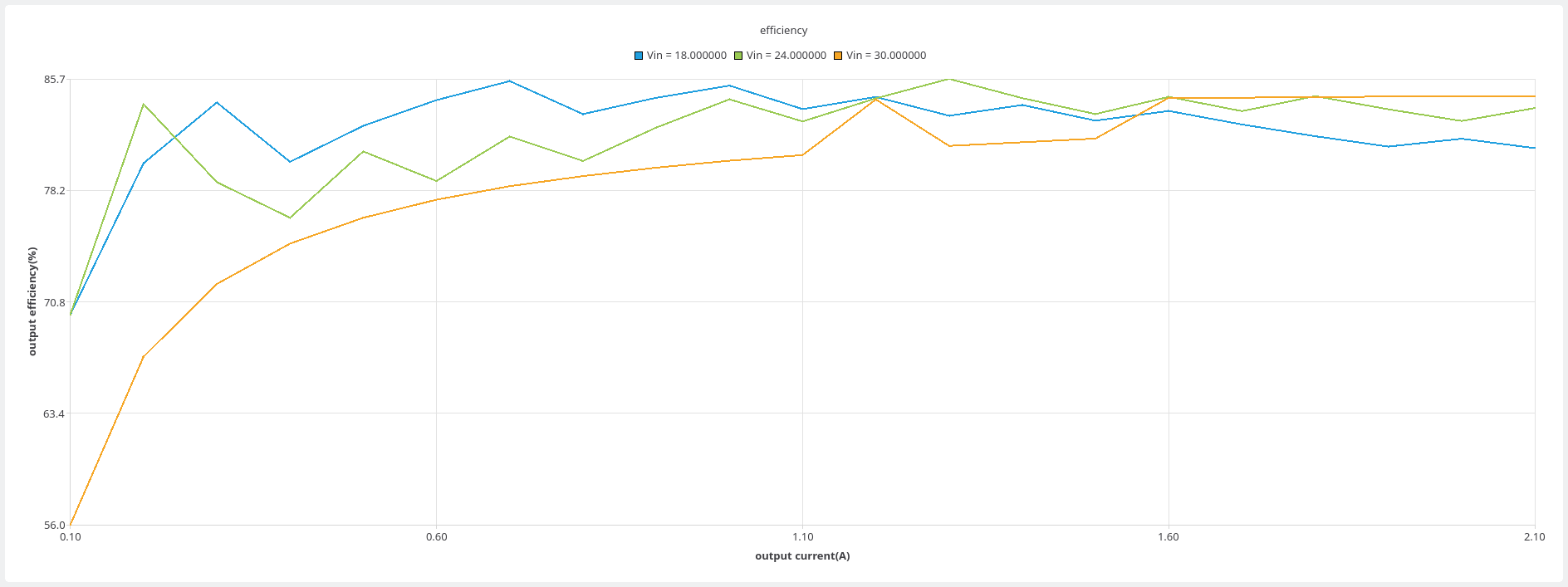
here are some outputs of the power tester. they are regulation and efficiency graphs for the flyback on the switchbox project
the power supply was also successful and had only one(two?) issue(s) which was that the input protection FET gates were not sufficiently protected and i had to fit the two nonpop zeners
the PSU regulates properly over the input range for 110% of the output current range(design=2A, test=2.2A) and is stable for more than 24hrs to within ten millivolts.
the efficiency isnt great, generally being in the upper 70%s but the measurement setup wasnt brilliant, the measured current values from the PSU have not been verified for correctness and may have a large amount of variance, if memory serves there is at least a 2% inaccuracy(was able to measure ~102% efficiency when the tester was in self-verification setup). the graph was also suspiciously spiky
i can finally claim victory over the LT8304!
the USB and ethernet(and therefore also clocking) have been verified before any firmware was flashed as the MCU has a vendor bootloader which may use USB or ethernet; the USB connection showed in dmesg and the ethernet BOOTP requests were visible in wireshark
the trigger subsystem was verified before fitment of the MCU or other comms interfaces and performed as required. later the exported power was loaded and the assembly thermals were reasonable
some firmware work has been done with a functional TCP connection and a couple of commands implemented. the relays have been tested using some temporary commands and perform as expected
so, early signs are good but there are still many unknowns, namely:-
- USB and ethernet at the same time
- full command set
- the chassis connectors are big and will need to be in a 4*8 arrangement, this needs to be drawn and made
- the upper PCBA is still TODO
the tool in the frontend is not desirable, it was produced to provide some insight into how best to proceed while also providing useful output(was used to verify that the switchBox PSU operated correctly(it did))
the plan is still to have a frontend that can be used to open and run tests that are stored in config files. how it will do this is still TBD...