blog
rimmer accepts an input file which contains TE and test definitions; the TE is then connected to and the tests will be run
the test definition part is still not fully thought out...
the new build system has an improved test system by enabling coverage and generating gcovr reports
there is now 100% coverage unit testing of the datastructures and >90% coverage of the utils directories. the utils are lower as there seem to be some redundant checks leading to never-followed branches. the pruning of these is planned
the new interface is easier to extend and to read
the testing was fun, the switchBox was connected to a toy keyboard from argos in such a way that each individual key could be pressed and the speaker was connected to an oscilloscope. the keys were then pressed in turn with the oscilloscope measuring the signals. this measurement was verified and was within a reasonable bound(given that the keyboard has lots of jitter and drift)
the current firmware can operate the switches and maintains counts of how many times a given contact has been closed(moved from NC to NO) as well as reporting the status
operation over USB and TCPIP are working
it is planned to add support for static IP addressing
the enclosure is coming along, the base holes have been drilled(but not countersunk) and the rear panel is marked up for the PCB mounted connectors. all front modifications are TODO
both the top and bottom PCBA have been produced
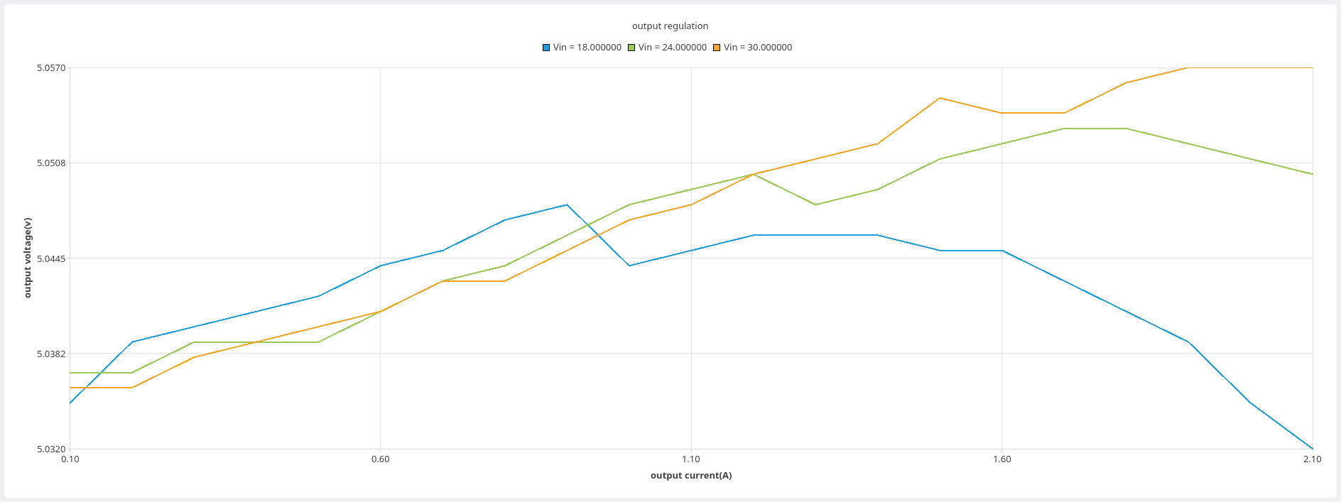
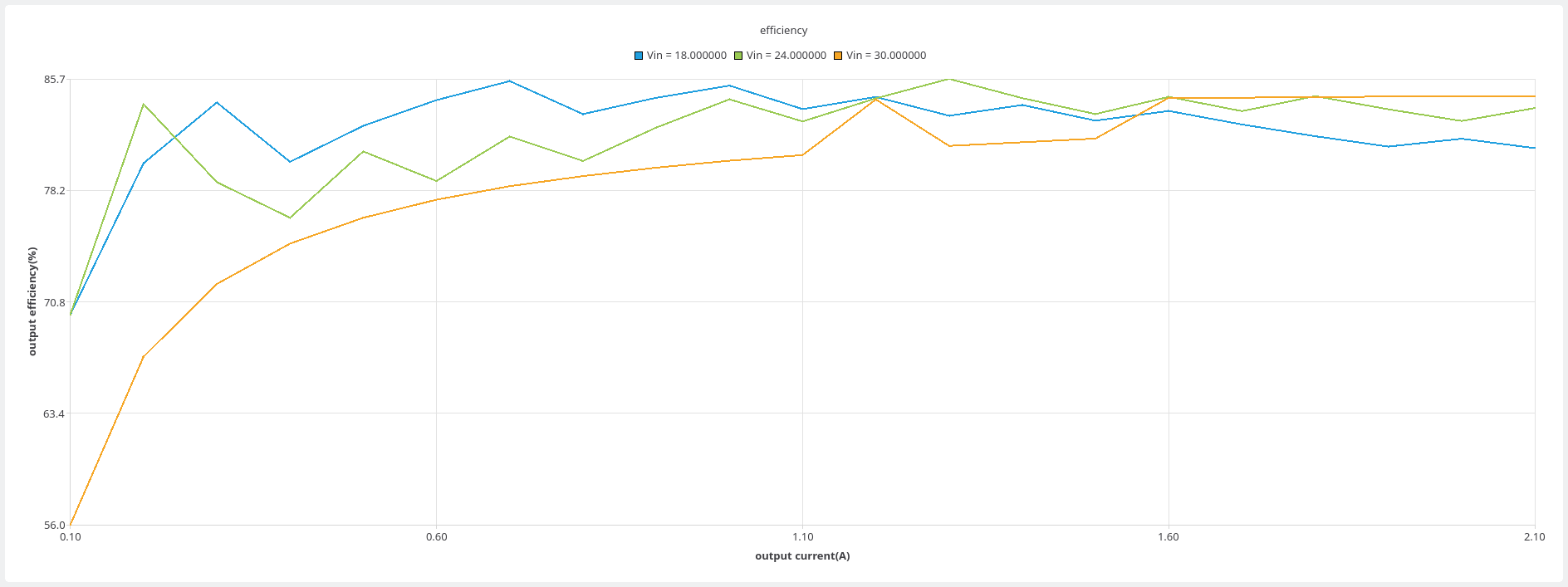
here are some outputs of the power tester. they are regulation and efficiency graphs for the flyback on the switchbox project

